
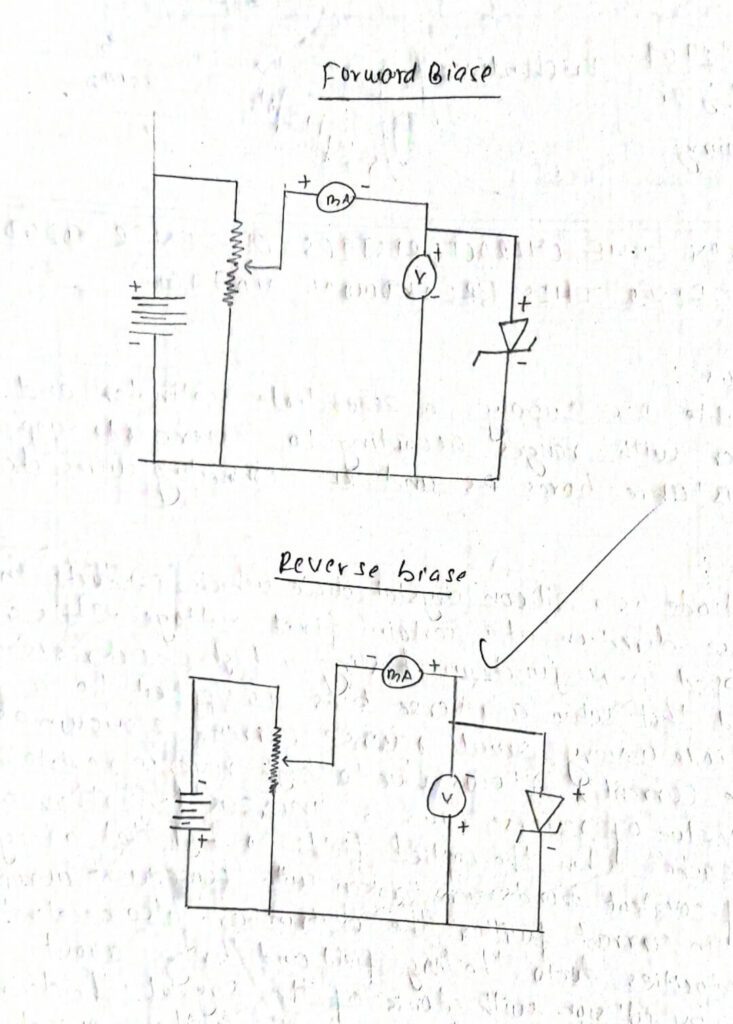
APPARATUS
A variable D.C supply, a Zener diode voltmeter and ammeter with ranges according to Zener diode supplied two resistance boxes RS and RL connecting wires etc.
THEORY
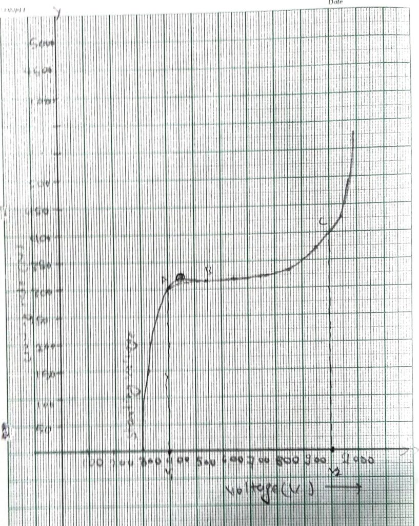
A Zener diode is a silicon crystal diode which conducts in the reverse direction at a certain fixed voltage . It is a highly doped P-N junction having a high back resistance; it is found that when a reverse bias is applied to a crystal diode a very small reverse current (known as leakage current) Flows due to high reverse resistance. As the value of reverse bias is increased further a stage reaches. When the applied fields are so high that a large number of covalent bonds are broken with consequent abrupt increase in current further the electrons are also accelerated to high velocities due to the large field and bring about ionization by collision with atoms of the crystal. The electron thus produces more free electrons due to further ionization by collision. This process is known as the avalanche process and gives rise to a very large current in the diode and the junction is said to be broken.
Due to the large increase in current the back resistance drops to a very low value. After the breakdown has Occurred the voltage across the junction remains constant over a fairly wide range.
The reverse voltage at which breakdown occurs is called breakdown voltage of Zener voltage. A Zener diode can be used as a voltage regulator to provide a constant voltage from a source whose voltage may vary over a sufficient range. The Zener voltage depends upon the semiconductor Material, amount of doping and method of producing the PM junction. Zener diodes can be obtained with breakdown voltage ranging from 2 volt to several hundreds volts by adjusting the concentration of the impurity in the materials producing the P.M Junction.
OBSERVATION
Least count for ammeter
10 division = 2 volt
1 division = 2/10 volt = 0.2 volt.
Least count for voltmeter
10 division = 5 volt
1 division = 0.5 volt
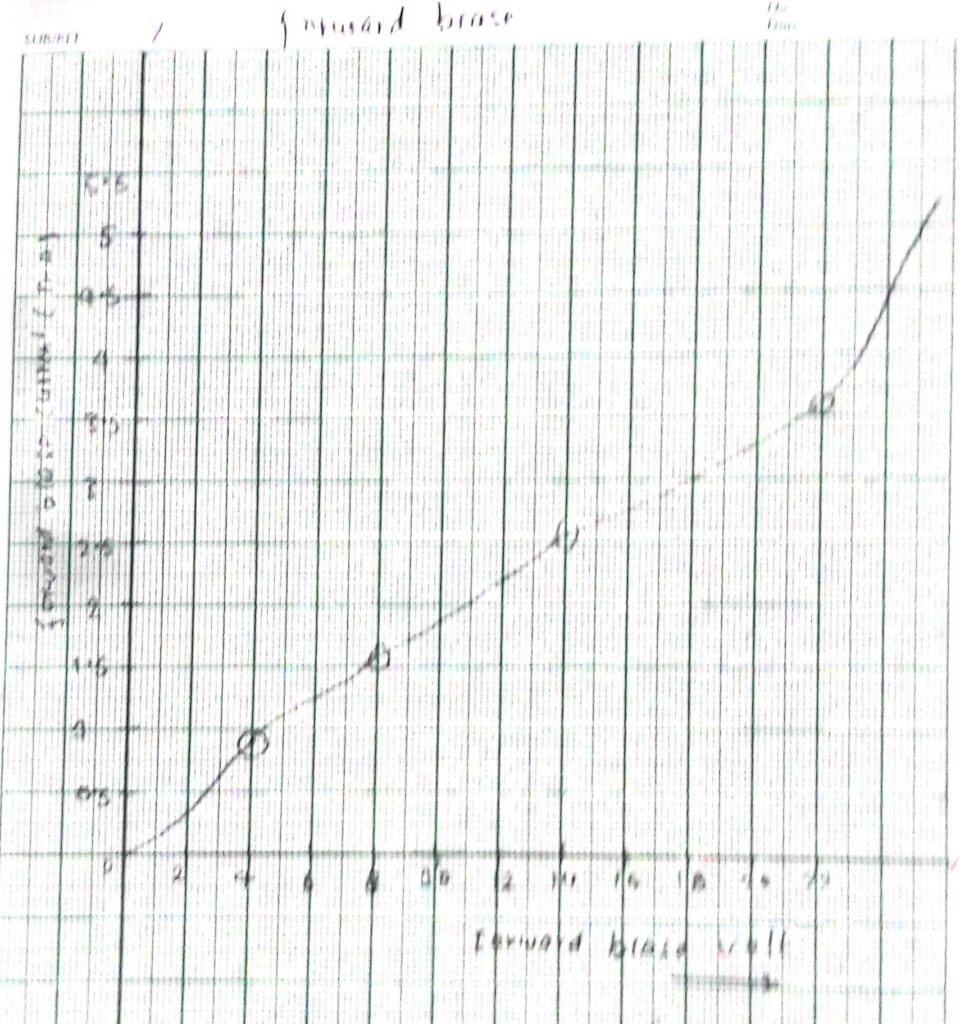
OBSERVATION TABLE FOR Forward characteristics
| S.N. | Current (I) (MA) | Voltage (V) |
| 1 | 2 x 0.2 = 0.4 | 3 x 0.5 = 1.5 |
| 2 | 5 x 0.2 = 1 | 9 x 0.5 = 4.5 |
| 3 | 8 x 0.2 = 1.6 | 16 x 0.5 = 8 |
| 4 | 13 x 0.2 = 2.6 | 29 x 0.5 = 14.5 |
| 5 | 18 x 0.2 = 3.6 | 45 x 0.5 = 22.5 |
| 6 | 28 x 0.2 = 5.6 | ∞ x 0.5 = ∞ |
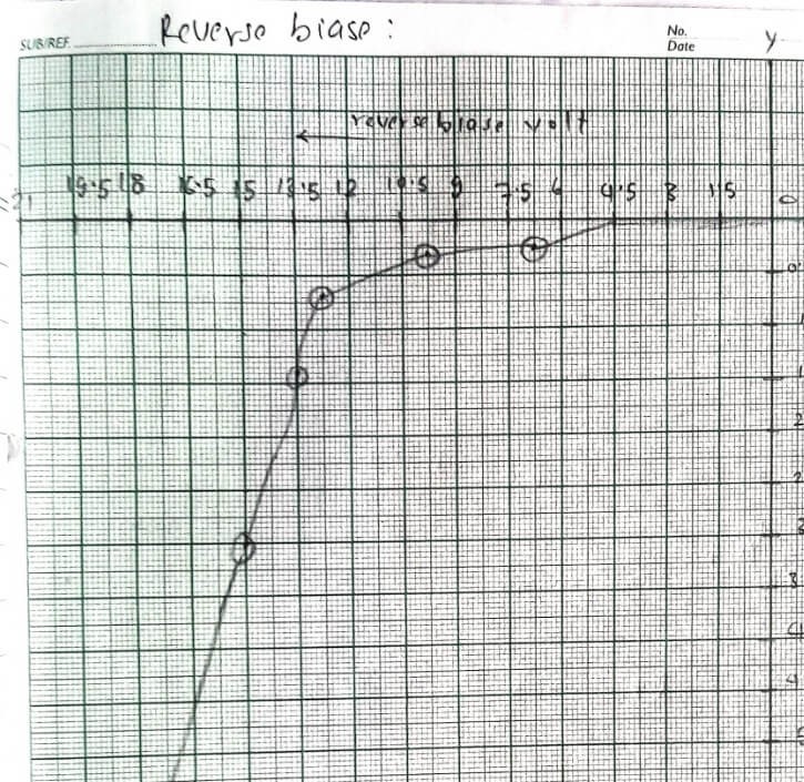
For reverse bias:
| S.N. | Current (I) (μA) | Voltage (V) |
| 1 | 0 x 0.2 = 0 | 0 x 0.5 = 0 |
| 2 | 0 x 0.2 = 0 | 2 x 0.5 = 1 |
| 3 | 0 x 0.2 = 0 | 4 x 0.5 = 2 |
| 4 | 0 x 0.2 = 0 | 6 x 0.5 = 3 |
| 5 | 0 x 0.2 = 0 | 10 x 0.5 = 5 |
| 6 | 0 x 0.2 = 0 | 14 x 0.5 = 7 |
| 7 | 1 x 0.2 = 0.2 | 17 x 0.5 = 8.5 |
| 8 | 1 x 0.2 = 0.2 | 20 x 0.5 = 10 |
| 9 | 3 x 0.2 = 0.6 | 25 x 0.5 = 12.5 |
| 10 | 7 x 0.2 = 1.4 | 27 x 0.5 = 13.5 |
| 11 | 15 x 0.2 = 3 | 30 x 0.5 = 15 |
| 12 | 26 x 0.2 = 5.2 | 35 x 0.5 = 17.5 |
| 13 | 39 x 0.2 = 7.8 | 40 x 0.5 = 20 |
| 14 | ∞ x 0.2 =∞ | 45 x 0.5 = 22.5 |
Explore More Physics Practicals | B.Sc. 2nd Year | T.U.
- Zener Diode Characteristics & Breakdown Voltage | Experiment Guide
- Determine Specific Rotation of Sugar Solution Using a Polarimeter
- Find Impedance of LCR Series Circuit & Calculate Quality Factor
- Determine Operating Voltage of G.M. Counter | Schematic & Guide
- Verify NAND Gate as a Universal Gate Using IC Chips
- Study NPN Transistor Characteristics in Common Base Mode
- Find Wavelength of Light Using a Diffraction Grating
- Find Wavelength of Sodium Light Using Newton’s Rings
- Determine Viscosity Coefficient of Water | Poiseuille’s Method
- To Determine Surface Tension Using Capillary Tube Method
- Determine Young’s Modulus by Bending Beam Method | PDF
- Determine Moment of Inertia & Angular Acceleration | Flywheel
- Determine Acceleration Due to Gravity & Radius of Gyration | Bar Pendulum
- Determine Modulus of Rigidity Using Maxwell’s Needle | PDF
- Study Charging & Discharging of Capacitor | Find Capacitance