APPARATUS REQUIRED
i) Compound pendulum
ii) Wedge
iii) A stopwatch
iv) A meter rod
v) Graph paper
vi) A Spirit level
THEORY
A compound pendulum consists of a rigid body which can oscillate Freely about a horizontal axis passing through it. The time period ‘t’ of a compound pendulum is given by,

Where ‘l’ is the distance of the point of suspension O from the center of gravity G and K is the radius of gyration about an axis through the center of Gravity. A Simple pendulum having the same time period as a compound pendulum is called an equivalent simple pendulum and its length measures the equivalent length L.
In the figure; the point C at a distance equal to the length of an equivalent simple pendulum from the point of suspension and the straight line passing through the center of gravity is called the center of oscillation.
The time period of the compound pendulum about a horizon axis through C is the same about O. The center of suspension and the center of oscillation are thus interchangeable.
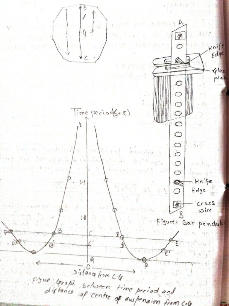
Actually, there are four points, two on either side of the center of gravity and collinear with it about which the time period of the compound pendulum is the same. If we select two points on either side of C.G. but not equidistant from then one of these corresponds to the center of oscillation. If the distance of one of them from C.G is l1 and that of the other is l2 then, Equivalent length L = l1+l2. The time period of a Compound pendulum.

The time period of the compound pendulum is minimum when the distance of the point of suspension from C.G is equal to the radius gyration.

Bar pendulum: A special type of a compound pendulum is used to find the value of g. It is called a bar pendulum and is shown in figure. It consists of a uniform metal bar having holes drilled along its length symmetrically on either side of the center of gravity. Two knife edges are placed symmetrically with respect to the C.G. As at A and B. The time period is determined about each hole by placing the two knife edges symmetrically about C.G. The distance of each of the Knife edges from the center of gravity are measured in each cos.
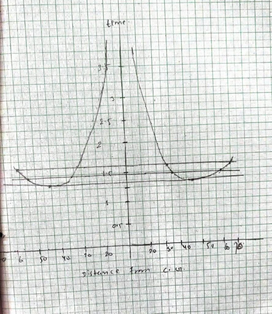
If the graph is plotted between the distance of the knife edges from the center of gravity taken along X-axis and the corresponding time period along Y-axis for a bar pendulum then the shape of the graph is shown in the figure.
If the horizontal line ABCDE is drawn it cuts the graph in points A, B and D, E about which the time period is the same. The point A and D or B and E lies on the opposite sides of the C.G. at unequal distances such that the time period about these points is the same. One of these corresponds to the center of suspension and the other to the center of oscillation. The distance
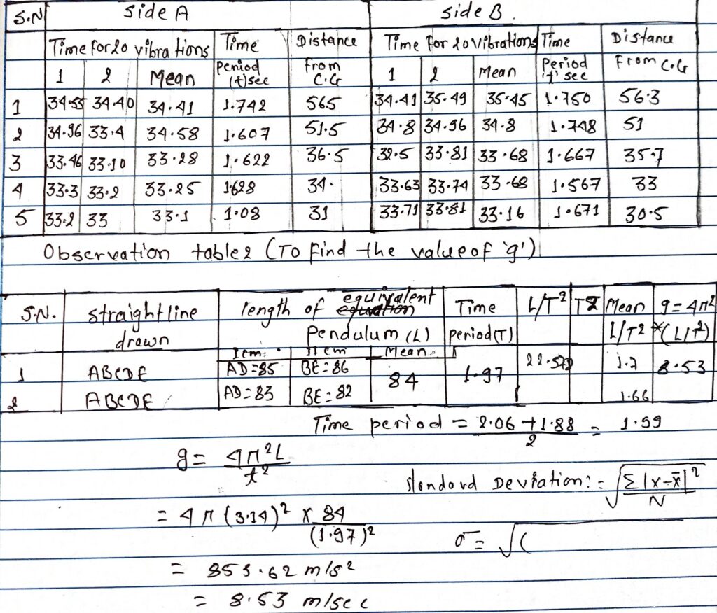
AD and BE give the length of equivalent simple pendulum ‘L’. If ‘T’ is the corresponding time period then,
T= 2π√L/g
Therefore, g= 4π2L/T2

PROCEDURE
i) Mork by chalk on two sides of the pendulum one side as A and other side as B.
ii) Balance the pendulum on a wedge and determine the position of its center of gravity. For most of the bar pendulum it lies at its center.
iii) Measure the distance between the C.G and the inner edge of the knife edge.
OBSERVATION
Observation table 1:

CONCLUSION
HENCE ,In this way, the acceleration due to gravity can be determined with the length of the bar pendulum.
PERCENTAGE ERROR
standard value of acceleration due to the gravity (g) = 9.8 m/s2
Observed value of acceleration due to gravity (g)= 8.53 m/s
percentage error = standard value – observed value/standard value x 1807
=9.8 – 8.53/9.8 x100%
= 12.695
PRECAUTIONS
i) The knife-edges should be horizontal and the bar pendulum parallel to the wall.
ii) Amplitude of vibration should be small.
iii) The time period should be noted after the pendulum has made a few vibrations.
iv) The two knife – edges should always lie symmetrically with respect to the C.G.
v) The distance should be measured from the knife – edges.
vi) The graph should be a free hand curve.
