APPARATUS REQUIRED
i) Electronic design experiment
ii) 220 Ω resistor
iii) 470 µF capacitor
iv) Multimeter
v) stopwatch
vi) Connection wires.
THEORY
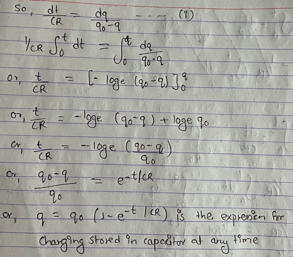
Let us consider the Risthe resistance of a resistor, V is the potential difference across and C is the capacity of a Capacitor to be charged.
let, I be the current in the circuit, Vc is the potential difference across the capacitor and VR be the p.d across the resistor then,
VR = IR and Vc = q/c where q be the charge stored in the capacitor in time T: then we have
V=Vc +VR = q/c +IR
or, V= q/c + dq/dt R
or, Cv-q = Cv dq/dt
or, dt/CR = dq/Cv-q here, cv = qo = maximum charge stored on capacitor
Discharging:
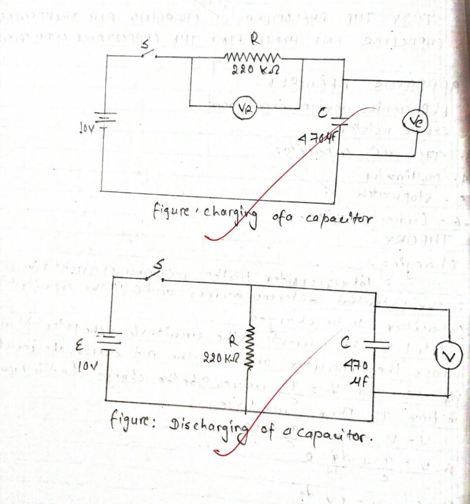
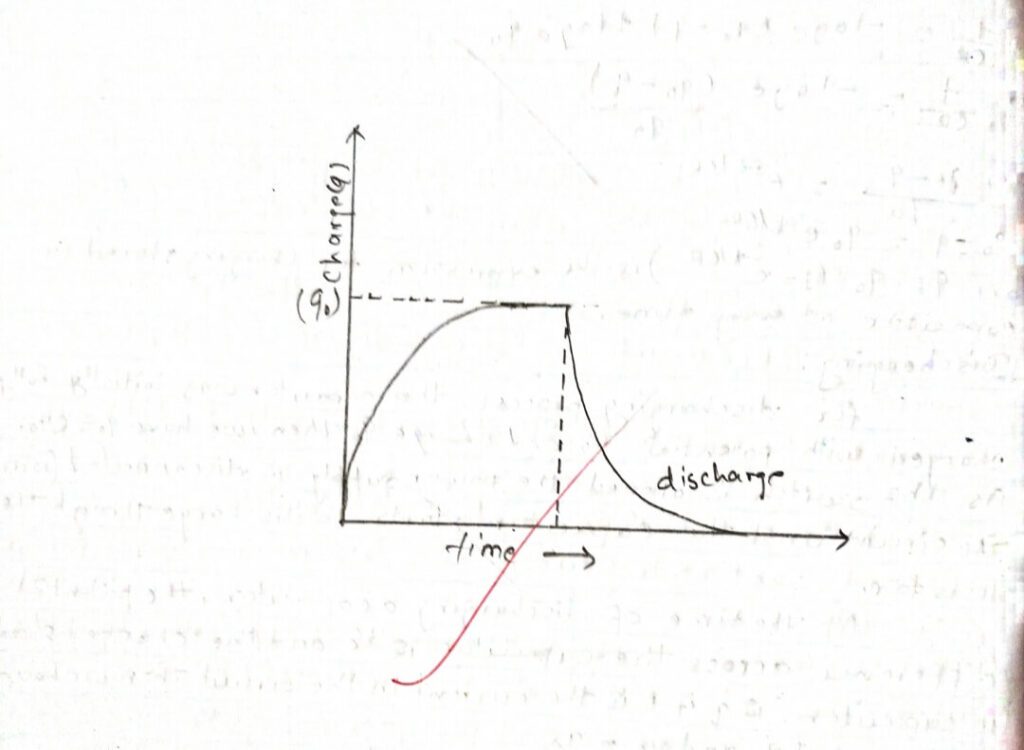
For the discharging process the capacitor was initially fully charged with potential Vo and charge qo then, we have qo = CVo. As the switch is opened the power supply is disconnected from the circuit and the capacitor starts to discharge through the resistor.
At the time of discharging a capacitor, the potential difference across the capacitor is Vc and the charged stored in capacitor is q if I is the current in the circuit then we have
Vc = VR = IR and Vc = q/c
Also,I = -dp/dt ‘Where negative sign indicates q decreases as time increases.
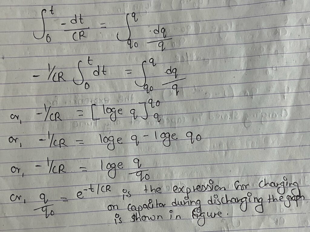
or, -dt/CR = dp/q
Integrating on both sides
PROCEDURE
Charging of a capacitor (Voltage Vs.Time)
i) Connect the circuit as shown in figure of charging of a capacitor.
ii) Turn on the power supply and set the output of the supply to10v.
iii) Close the switch S and reset the stopwatch.
iv)Record the time t1 Corresponding to Vc reaching value indicates in table 1.
v) Reset the stopwatch and repeat, steps above for time corresponding to the same values Vc and record in t2 table 3.
vi) Calculate average time and plot a graph for Vc versus tang which determine T and calculate
OBSERVATION
| S.N. | Voltage (v) | log(v) | Time (t) sec |
| 1 | 10 | 1 | 170 |
| 2 | 7.5 | 0.875 | 181 |
| 3 | 5 | 0.699 | 190 |
| 4 | 2.5 | 0.898 | 196 |
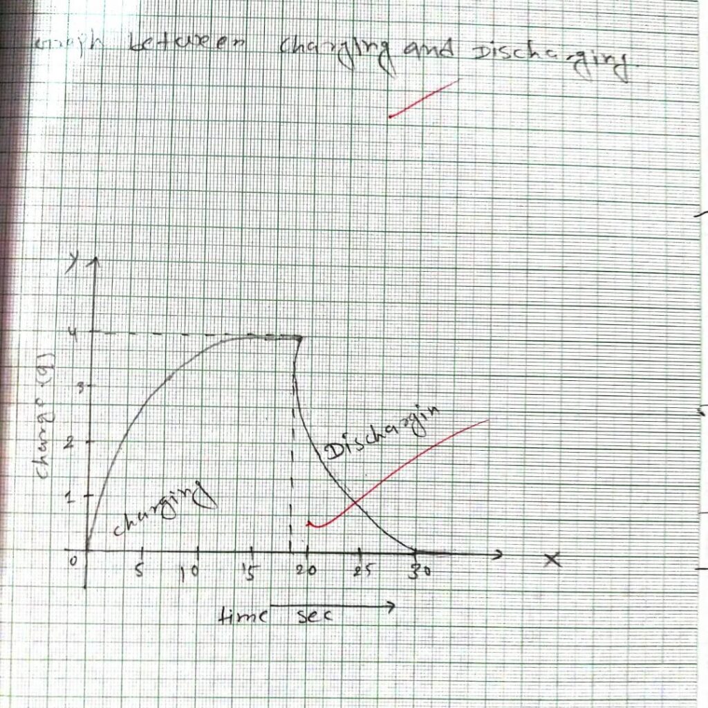
CALCULATIONS
Resistance (R) = 0.1X 10⁶ Ω
Slope of graph between log(v) and time (t)
(170,2) = (x1 y₁) or, (190,0.699) = (x2,y2)
Slope = y2-y1/x2-x1 = 0.699-190/190-170 = -0.0150
Therefore, slop = -tanθ = -(-0.015) = 0.015
Now capacitor (c) = 1/R x slope of graph
= 1/0.1×106x0.015 = 1×10⁻³ F
RESULT
The capacitance of a giveN capacitor is found to be 1×10⁻³ F
CONCLUSION
Thus we studied the charging and discharging properties of the capacitor in the Rc circuit.
PRECAUTION:
i) The positive parts of the capacitor should be connected to the positive terminal of the battery and vice versa.
ii) The circuit arrangement, should be appropriate for charging and discharging
iii) for charging, the capacitor and the resistor should be connected in series with the source.
iv) For discharging, the capacitor and the resistor only should be connected.
