
APPARATUS REQUIRED
i) A uniform regular beam
ii) Two knife edges
iii) Scale ruler
iv) A hanger
v) Micrometer Screw
vi) Vernier caliper
vii) Slotted half kg. weight
viii) A galvanometer
THEORY
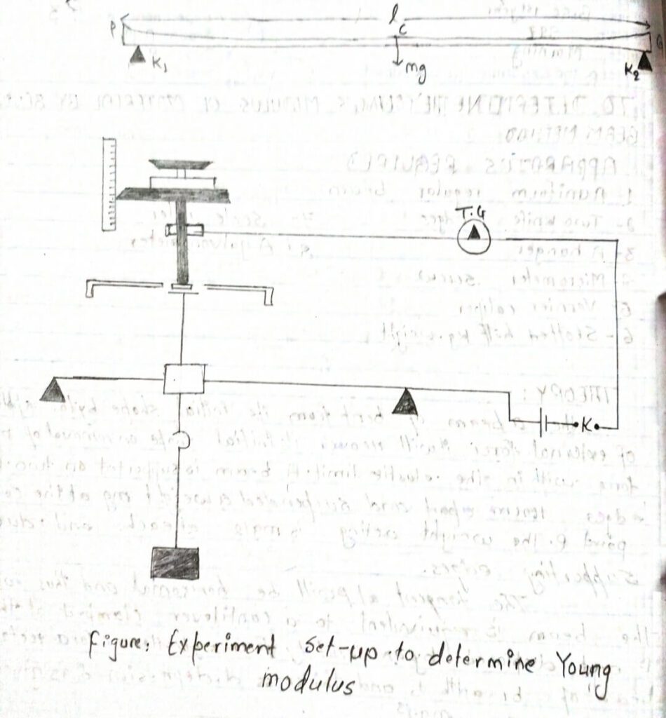
When a beam is bent from its initial shape by the application of external force, it will recover its initial shape or removal of applied force within the elastic limit. A beam is supported on two knife edges 100 cm apart and suspended a weight mg at the center point P. The weight acting is mgl2 at each and due to supporting edges.
The tangent at p will be horizontal and thus each of the beam is equivalent to a cantilever clamped at the point P and displaced by an end by force mgl2. Hence, for a rectangular beam of breadth b and thickness d, depression 𝛿 is given by.
𝛿 = mg.l3/4Ybd3
Where Y is the young’s modulus of the material of the beam
Y = mgl3/4Yb𝛿d3
Where l is the length of the beam between knife edges.
PROCEDURE
i) Place the bar on two knife edges as shown horizontally so that the marked line lies equal distance from the CG of the bar. Then suspend the hanger placing weight from the stirrup resting on the bar at the middle of the knife edge.
ii) Now connect the electric circuit.
iii) Now Bring the miscometer or spherometer in contact with the beam when it is unloaded and note the readings.
iv) Now, Turn the screw in one direction till the contact is just made shown by deflection in the galvanometer.
v) Decrease the load in steps of 0.5 kg and note the corresponding reading as before.
vi) Take the mean of the two readings which gives the required reading for each load.
vii) Then find the depression for 1 kg taking the difference between two reading load differences of 1 kg.
viii) Now, using screw gauge and vernier calipers determine the thickness and breadth of the bar.
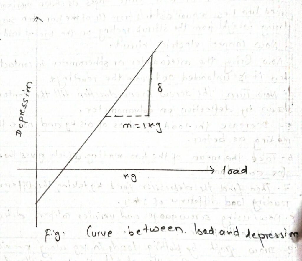
ix) Draw graph by plotting loads in lag along x axis and depression along the y-axis. The graph will be straight line passing through the origin from graph ; find out mgl3/𝛿 and put the value in above relation and find the value of Young’s modulus.
OBSERVATION
length of the beam between the two knife edges l = 0.885m
Reading for breadth of the beam = 3.3cm = 0.033m
V.S. of vernier caliper = (u𝛿d) = 86
for thickness of the beam
Main scale reading (m.s.d) = 5mm
least count for screw gauge (L.C) = 0.01mm
Then, d= M+V.S+L.C
= 5+ 86X0.01
= 0.00586 m
Reading for the depression of the beam:
least count for micrometer =0.5mm
fo division = 5mm -> 1 division = 0.5mm
| S.N | Load in kg | Micrometer reading while load is increasing | Micrometer reading while load is decreasing | Mean reading (mm) | Depression for 2kg mass (mm) | Mean depression |
| 1 | 0 | 4 | 3.5 | 3.75 | ||
| 2 | 0.5 | 3 | 3 | 3 | 2.5 | |
| 3 | 1 | 2.5 | 2.5 | 2.5 | ||
| 4 | 1.5 | 1.5 | 2 | 1.75 | 0.0 | 2.5×10⁻³m |
| 5 | 2 | 1 | 1.5 | 1.15 | ||
| 6 | 2.5 | 0.5 | 0.5 | 0.5 | 2.5 | |
| 7 | 3 | 0 | 0 | 0 | 2.5 |
CALCULATION
Mean breath of beam ‘b’ = 0.033m
Mean thickness of beam (d) = 0.00586m
Mean depression of beam = 2.5x 10⁻³m
Young’s Modulus “Yo” = mgl3/4b𝛿d3
= 2 x 9.8x(0.885)3 / 4 x 0.033x (0.00586) ³ x 2.5×10-3
= 2.04 × 10¹¹ N/m2
percentage error:
standard value of young’s modulus of iron bar,
(Ys) = 2.1 × 10¹¹ N/m2
Percentage error = (Ys-Yo/Ys)x100%
=(2.1×10¹¹-2.04×10¹¹/2.1×1011)x100%
= 2.80%
CONCLUSION
Hence, the Younger modulus of given beam is calculated to be 2.04 × 10¹¹ with percentage error 2.80%
PRECAUTIONS
i)The knife edge should be rigid and fired on a rigid support.
ii) The Knife edge should be at equal distances for the center of the bar. The stirrup should be parallel to the knife.
iii) The weights should be placed exactly at the center of that asymmetrical Loading of the bar.