APPARATUS REQUIRED
i) An inductance
ii) A resistance
iii) A condenser
iv) Ac ammeter and voltmeter
v) Step down transformer
vi) Rheostat
vii) Key and connecting wires
THEORY
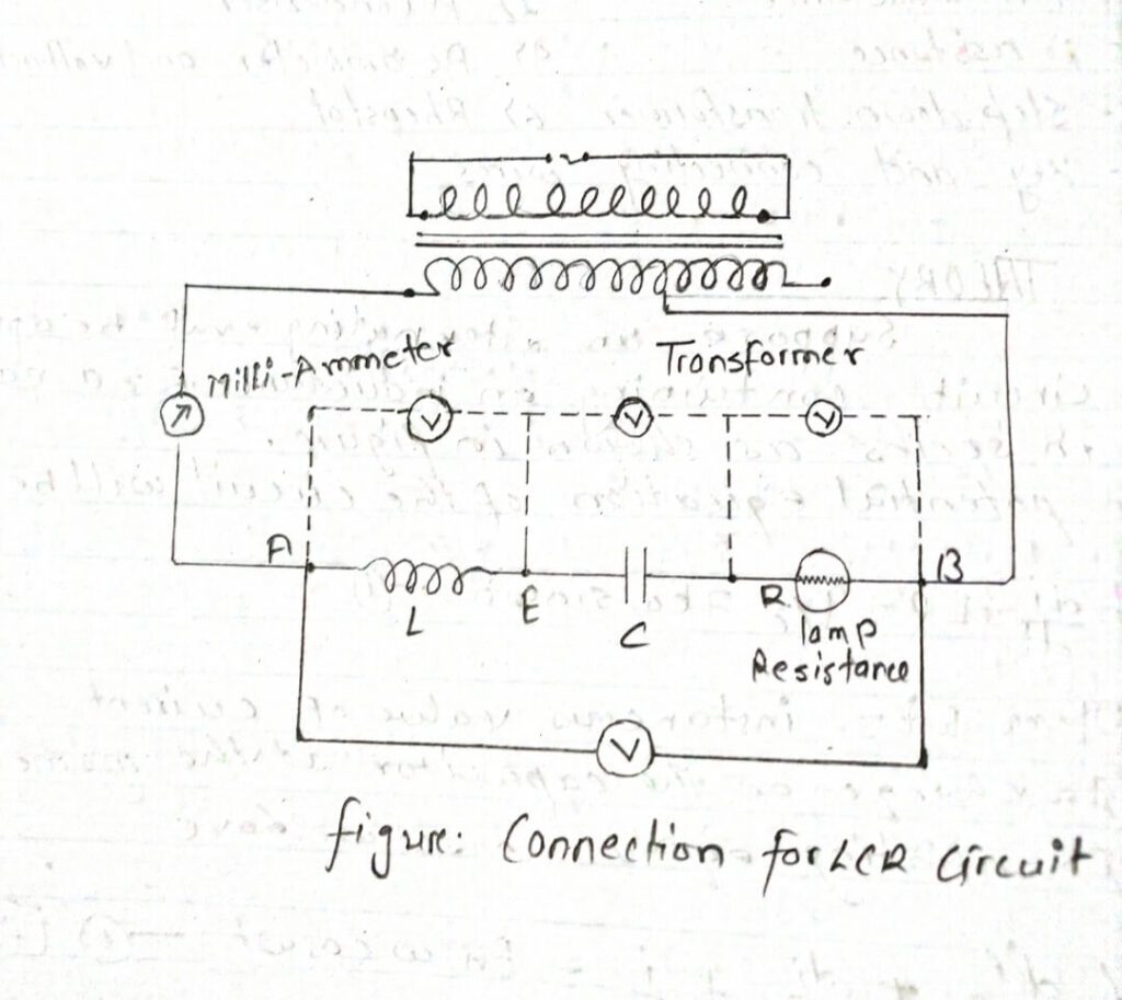
Suppose an alternating emf be applied to a circuit containing an inductance R=a capacitor C in series as shown in figure.
The potential equation of the circuit will be given by
L di/dt +IR+q/c = Eo sinwt…………. (i)
Where i= instantaneous value of current
I= charge on the capacitor at the moment
Differentiating equation (ii) once we have ,
L d2t/dt2 +di/dt +i/c = Eo w coswt ……….. (ii) [ therefore, dq/dt = i]
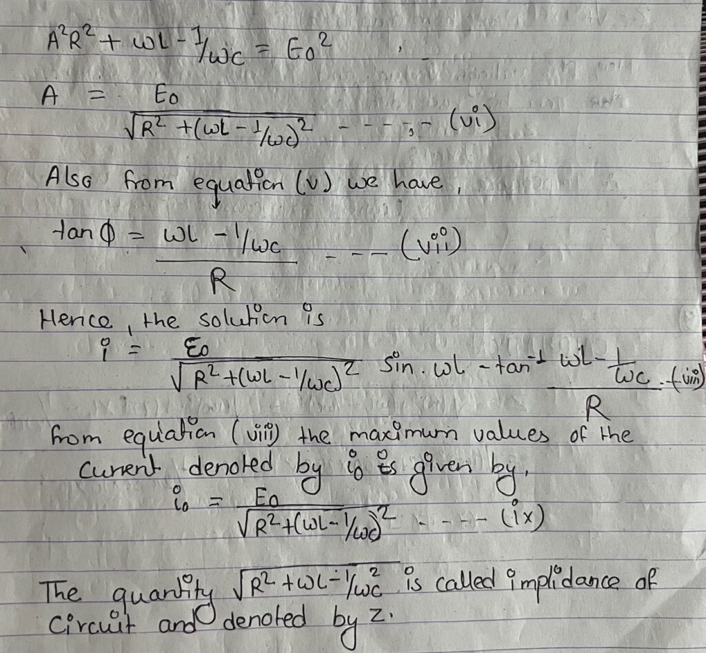
Let, the solution of the equation be i= Asinwt where A and are to be determined
Therefore, di/dt = Aw cos(wt-ɸ) and d2i/dt2 = -Aw2 sin(wt-ɸ)
Substituting the value of in equation (ii) we get
-LA w2 sin(wt-ɸ) +RA wcos(wt-ɸ) +A/C sin(wt-ɸ) = Eo w cos wt ………..(iii)
Comparing the coefficients of cosα + and sin wt on the two sides of the equation (iii) we get,
AR Cosɸ + A(WL – 1/WC ) sinɸ = Eo ……….(iv)
And -AR sinɸ + A(wl-1/wc) cosɸ = 0 …….. (v)
Now, squaring on both side and adding equation (iv) and (v) we get,

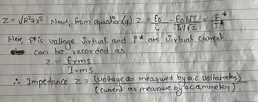
Quantity wL and 1/wc are known as inductive reactance and capacitive reactance and X is the total reactance.
The impedance of the circuit is expressed as:


PROCEDURE
i) The reading of ammeter and voltmeter is recorded by the thermostat.
ii) The graph is plotted between virtual E* and virtualia i* ampere.
iii) The impedance of circuit is also calculated from the known value LCR and the frequency cm
of a.c. mains.
BSERVATION
Resistance of resistor (R) = 100 ohm
Inductance of inductor = 298×10-3
Capacitance of capacitor (C) = 10×10-3 F
Angular frequency (W) = 2πf = 50 Hz
least count of voltmeter = 0.25V
least count of ammeter = 10-3A
below the observation.
| S.N. | Voltmeter reading vol1 | Ammeter reading in Aper | V/I ohm | Mean z=V/I Ω |
| 1 | 1×0.25 = 0.25 | 9×10⁻³ | 27.78 | |
| 2 | 5×0.25 = 1.25 | 18×10-3 | 69.44 | 67.46 |
| 3 | 10×0.25 = 2.5 | 30×10-3 | 83.33 | |
| 4 | 15 x 0.25 =3.75 | 42×10-3 | 89.286 |
CALCULATION

RESULT
The impedance of the circuit from observation table = 67.56Ω and 67.56 from calculation.
CONCLUSION
Hence the impedance of the given or circuit can be calculated.
PRECAUTIONS
i) The ammeter and voltmeter must be an accurate measuring instrument.
ii) The given condenser should have working voltage greater than a.c main voltage.
iii) The inductance used in the experiment should have a proper use in the experiment to current waiting so that it may not get over heat when current is passed through it.
